How to build an RGB LED Board
by Joshua Hart, Design Enterprise Studio Member , March 2022
Hi, I am Josh, a final year student in Digital Media who enjoys the physical building of computing devices as well as interfacing with them using software environments. This article will walk you through the necessary steps so you can build yourself a decent size RGB display board at home.
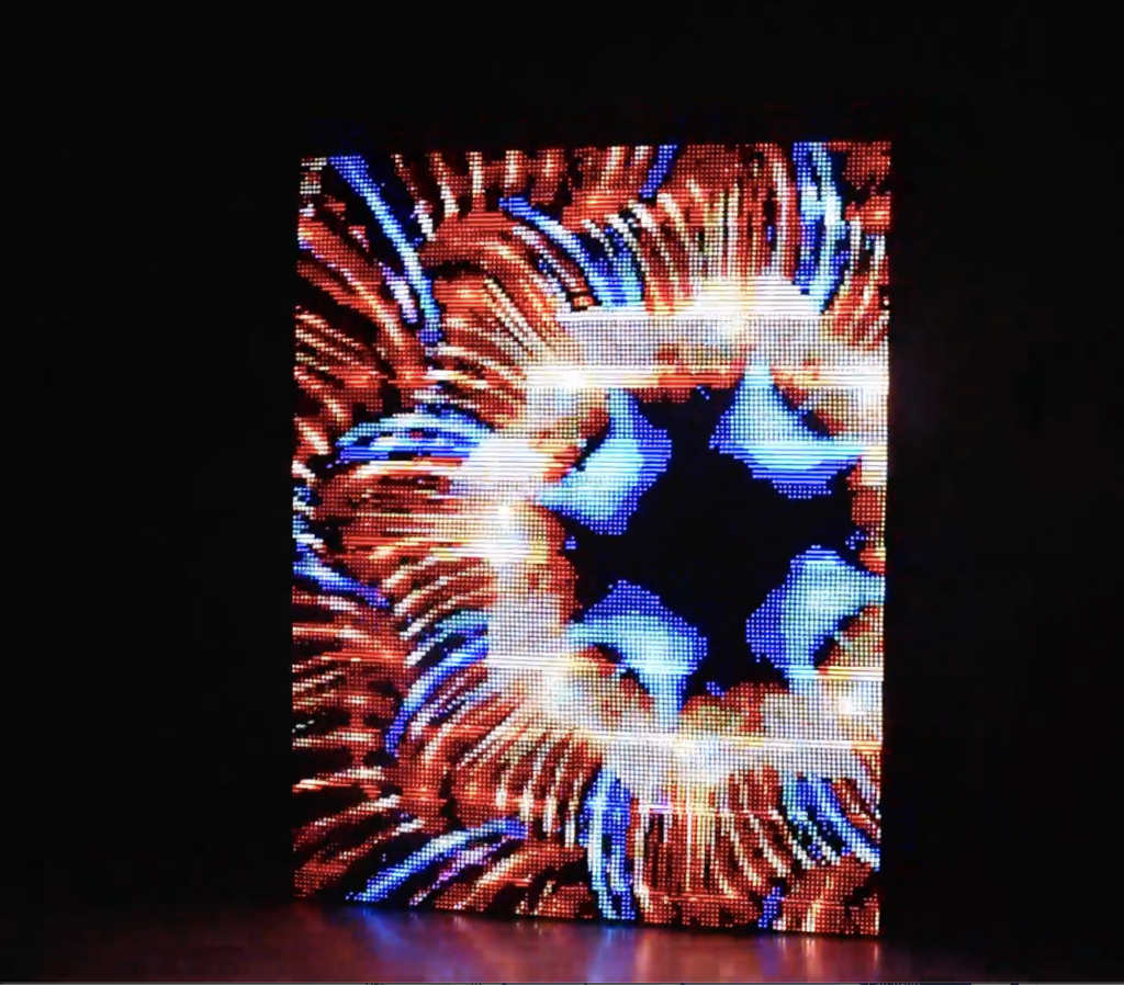
RGB LED panels have long been recognised for their large scale and bright presence at live music shows/ festivals and are now rapidly becoming the go-to display board for advertising content and information in our cities. The modular nature of the boards allows for easy configuration, which means they can fit any space. This and the ease of updating the boards remotely with new content make it a no-brainer for advertising. Since starting this project I have been collecting examples of RGB display boards on my portfolio site here: https://josh1hart.co.uk/rgb-matrices-baggator.
What you will learn:
In this blog post I will be helping you make a RGB matrix of 4 panels. This number has been chosen as it will provide you with the necessary knowledge of how to daisy-chain the panels together. Once you have got a basic understanding of this you can scale it up and down to any number of panels you like.
What you will need to buy:
| Product name | Price | Quantity | Link |
RGB LED Matrix Panel – 32×64 pixels 4mm pitch 256 x 128 x 14.5 (mm, L x W x H) | £45 | 4 | Link |
| 2.1mm Plug/Jack to Screw Terminal Block – Female | £2.70 | 1 | Link |
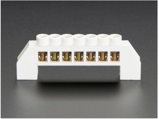
| Power Distribution Bus – 7 x 6mm diameter solid brass | £1.70 | 2 | Link |
| Raspberry Pi 3 Model B | £33.90 | 1 | Link |
| Pibow 3 B+ Coupé (Raspberry Pi 3 B+, 3, & 2) – Coupé Ninja0 | £8.40 | 1 | Link |
| SanDisk, 16 GB, Class 4 Memory Card with SD Adapter | £4.99 | 1 | Link |
| Adafruit RGB Matrix Bonnet for Raspberry Pi | £14.10 | 1 | Link |
| 5V 4A plug | £13.99 | 1 | Link |
| Electrical wire kit | £8.99 | 1 | Link |
| Total | £267.77 | 13 items |
You will also need:
- Mouse (Wireless recommended)
- Keyboard (Wireless recommended)
- Monitor
- Wire cutter
(My assumption is that you have these items and they will not need to be purchased)
Stage 0 (Soft & Hardware Preparation):
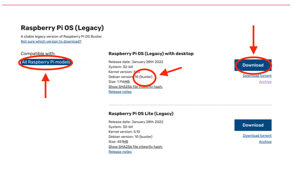
Before the build can really start, a particular version of Raspbian OS will need to be installed onto the 16GB SD card you have bought for the project.
Navigate to the Raspberry Pi website (https://www.raspberrypi.com/software/operating-systems/) and make sure to download both the Raspberry Pi Imager and the buster version of Debian. This will be essential to making the libraries and content work. Open the Imager app to install Debian (buster) onto the SD card. This completes the software preparation.
Next steps:
- Put together the Raspberry Pi case
- Place the SD card into the Raspberry Pi slot
- Insert the Adafruit Hat onto the GPIO of the Raspberry Pi
- Connect IO: keyboard, Mouse & Monitor
- Connect and power up the Raspberry Pi
Stage 1 (Physically Build and Wiring the Panels):
Now that you have prepared and installed most of the necessary software for the RGB LED panels, you can move towards connecting the panels together.
Each panel will require a power supply and a data connection to work. While working with power and data cables it is best practice to switch all power off; including the power to the Raspberry Pi.
Data cable:
- For the first panel we can connect the data ribbon provided into the input slot of the panel and the other end to the top of the Adafruit hat, which is positioned on top of the RPI. (Remember you should have already connected the Adafruit hat, as described in Stage 0 Preparation)
- After this, you basically need to connect the data output of the previous panel to the data input of the panel you are adding.
Power and Ground cables:
Setting up power for each display is a more challenging task. The power cables provided with the displays come as plastic connectors, which are designed for direct use with the panels on one end, and with a 2-metal prong on the other end.
- This plastic connector is designed to be fitted only one way, so please take caution plugging it correctly into the panel.
- At the other end of the power cable you have a power and a ground wire, with 2 metal prongs for each.
- These prongs are best cut off, using a cable cutter to cut the outer casing and exposing the copper wiring threads. Twist the treads of each cable separately.


4. The copper threads of both the live (red) and ground (black) wire must then be plugged into separate power distribution buses. To further clarify, as this is very important:
All live (=red) wires should be connected to one and the same power bus. Let’s call this the “live bus”. All the ground (=black) wires must be connect to a separate power bus, the “ground bus”.
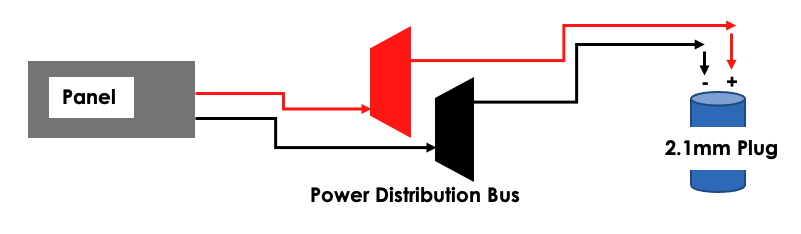
5. Both the “live bus” and the “ground bus” must then be connected with the extra wire purchased to the 2.1mm plug. This step may require you to use the cable cutter tool again, as you will need to perform further actions similar to the one done to the live and ground wires.
You will need to repeat the above five steps for all data and all power connections to all panels.
Next: Powering Up and Assembling the Bigger Board
You can now connect the power brick to the 2.1mm plug. This will provide all the panels with power.
Assembly: each panel includes a set of magnetic screws that can be used to snap the panels into a metal frame. This is useful, but you may wish to build your own non-magnetic frame. In this case, please note: if you are planning to replace the magnetic screws with regular ones it is vital you check the length. The RGB boards are very delicate and if the screws you use are planning to use are just slightly too long it could cause permanent damage to one or more individual LEDs (= you will have a black dot in the middle of your display). On the other hand, screws cut too short may snap off.
Stage 2 (installing the rpi-rgb-led-matrix):
In stage 0 we installed an operating system onto the Pi. Next, let’s install the libraries used to show content on the RGB boards:
Open the command line interface and
- Create a directory for the library: mkdir [Name-Of-Folder]
- Move into this folder with: cd [Name-Of-Folder]
- Make sure the Pi is connect to the internet
- Install library with: git clone https://github.com/hzeller/rpi-rgb-led-matrix/
Once the library has been installed:
- cd into the /lib folder with: cd ./rpi-rgb-led-matrix/lib
- now type: nano Makefile
- within nano Makefile, we need change the (HARDWARE_DESC). We will be changing this from the default (regular) to (adafruit-hat). This is telling the library that we are using an adafruit hat.
- Within Makefile we made also need to change the (SLOWDOWN_GPIO). This is commented out at first and must be uncommented. For my board I have changed the default value from 1 to 5. Without this, the board would run too quickly and anything attempted to be displayed on the board was freaking it out.
- You can now run examples!
- Exit the lib folder with the (cd ..) command and enter the examples folder with (cd ./examples-api-use)
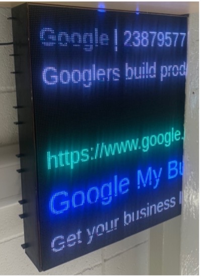
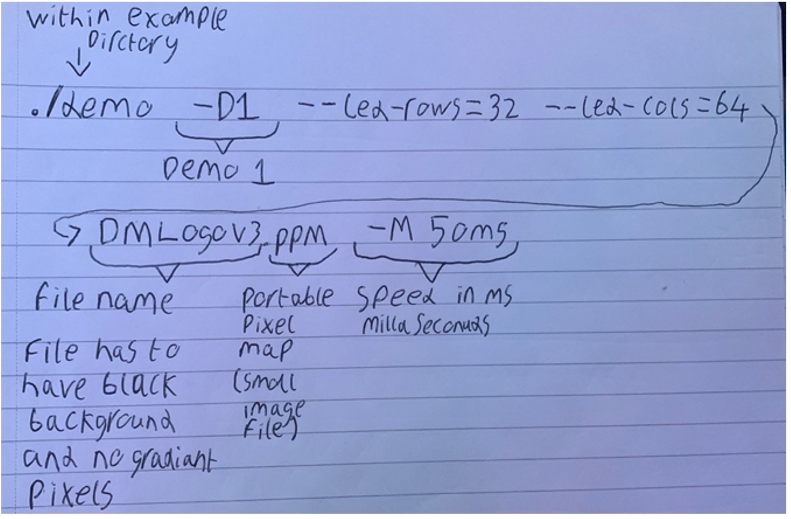
- In the image below you can see how a demo command is structured (if you leave out the -D command, the library will give you a list of options to choose from)
Here in this example I’m instructing the Pi to scroll an image. The library you have installed so far includes different examples for viewing images and text. But for some projects this may still not be enough.
Stage 3 (install rpi-fb-matrix):
This library translates the primary video output of the Raspberry Pi onto the RGB Matrix. This setup will be very similar to the installation of rpi-rgb-led-matrix.
- Open the command line interface and navigate to the [Name-Of-Folder]
- Install the library with: git clone –recursive https://github.com/adafruit/rpi-fb-matrix.git
- After this run: sudo apt-get update
- Then: sudo apt-get install -y build-essential libconfig++-dev
- Now we must build the project by running: make
- We can now use: nano matrix (this line of code opens a config file for us to edit). Once within the matrix config file, we can change a range of setting dependent on your displays and configuration of these displays.
- Things you must change to fit your own configuration:
- Display width and height (this is the dimension of the big panel with all panels in their wired, final configuration)
- Panel width and height (This refers to each individual panel)
- Chain length (the number of displays being chained together)
- We can also think about crop origin (with this commented out, the primary output will be scaled to fit onto the total number of panels)
- Finally but most importantly, we must tell the library how the panels are arranged. As explained below:
Example 1 (4 panels):
panels = (
( { order = 1; rotate = 0; }, { order = 0; rotate = 0; } ), < The RPi plugs in here
( { order = 2; rotate = 180; }, { order = 3; rotate = 180; } )
)
Example 2 (6 panels):
panels = (
( { order = 2; rotate = 0; }, { order = 1; rotate = 0; }, { order = 0; rotate = 0; } ),
( { order = 3; rotate = 180; }, { order = 4; rotate = 180; }, { order = 5; rotate = 180; } )
)
Imagine this chain as a snake that curves around from row to row. It is also important to keep in mind that it is likely you are flipping the displays upside down every other row to allow for the connections to the next row. This means you must rotate the panels by 180.
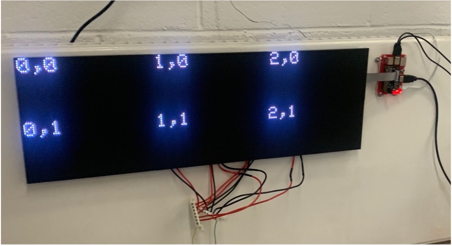
- Before you run the code to see the primary display, you may want to run a display test. This is important to check that the configuration you set up in the previous step has been done so correctly.
- Run: sudo ./display-test –led-slowdown-gpio=4 matrix.cfg
6. Now that you have the correct arrangement of the panels, you can run the library
- Run: sudo ./rpi-fb-matrix –led-slowdown-gpio=4 –led-gpio-mapping=adafruit-hat –led-pwn-bits=4 matrix.cfg
- This code above has extra flags to reduce the colour depth, increase the performance and decrease any flickering on the panels.